Sine wave inverter SG3525
In this post we will discuss two methods of designing pure sine wave inverter circuits using 555 IC based SPWM processing. In the first concept we connect the 555 processors directly with the SG3525 out. [pdf]FAQs about Sine wave inverter SG3525
What is a sg3525 inverter?
The SG3525 is a popular integrated circuit that is widely used in the design of sinusoidal pulse width modulation (PWM) inverters. The circuit diagram of a pure sine wave inverter using the SG3525 is relatively simple. It consists of an SG3525 chip, a few electrical components such as resistors, capacitors, and diodes, and a power transformer.
What is sg3525 PWM inverter circuit diagram?
Let us take a look at the SG3525 PWM Inverter Circuit diagram and discuss its designing principle. SG3525 can control the output voltage of the inverter. It is also useful in driving MOSFET IRF520 connected to a transformer. Both MOSFET is used as a low-side connection.
What is sg3525 IC?
The SG3525 is a versatile PWM (Pulse Width Modulation) controller IC commonly present in inverter circuits to convert DC to AC at either 50Hz or 60Hz. Here's a PWM based SG3525 inverter circuit with working. 1. Components Required: 2. Circuit Description:
What is a sg3525 controller?
The sg3525 is a pulse width modulation (PWM) controller that is commonly used in inverter circuits. It generates a square wave signal that can be modified to produce a sine wave output. The inverter circuit diagram typically consists of the sg3525 controller, a power stage, and a feedback loop.
Sine wave inverter voltage at each pole
A sine wave inverter converts DC power into AC power, mimicking the smooth oscillation of a natural sine wave. The term "voltage at each pole" refers to the voltage measured between the inverter's output terminals (positive and negative poles). This parameter is critical for ensuring stable power. . The three most common types of inverters made for powering AC loads include: (1) pure sine wave inverter (for general applications), (2) modified square wave inverter (for resistive, capacitive, and inductive loads), and (3) square wave inverter (for some resistive loads) (MPP Solar, 2015). controlled turn-on and turn-off. [pdf]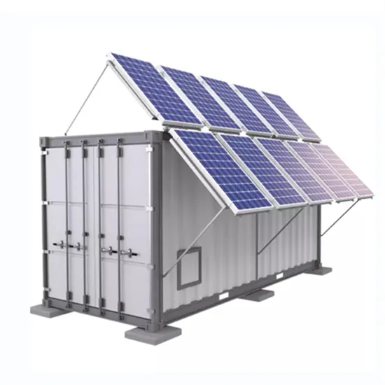
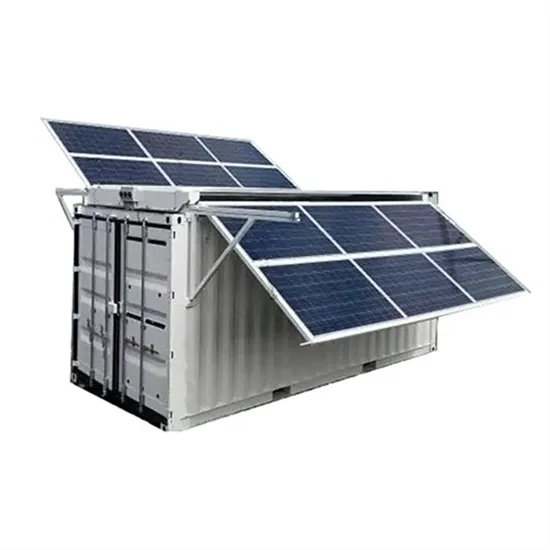
Outdoor inverter sine wave
This guide includes an overview of the top 5 pure sine wave solar inverters designed for RVs, homes, trucks, and off-grid solar systems. . Shop products from small business brands sold in Amazon's store. HouseAndBeyond is reader-supported. Learn more about our process here Planning long camping, RV, or boat trip? Or working at a. . Did you know that only about 15% of off-grid sine wave inverters actually deliver clean, reliable power exactly like mains electricity? I've tested dozens, and trust me, the difference is huge. The car inverter has a conversion efficiency of greater than 91% during normal working and low no-load losses 【PURE SINE. . [pdf]
Sine wave inverter for weighbridge
In this post we will discuss two methods of designing pure sine wave inverter circuits using 555 IC based SPWM processing. In the first concept we connect the 555 processors directly with the SG3525 out. [pdf]FAQs about Sine wave inverter for weighbridge
What is modified sine wave inverter?
Now it's time to complete the circuit of Modified Sine Wave Inverter. The complete sine wave inverter can be designed using full bridge circuit and a step up transformer. The aim of this project is design an inverter which can output a quasi sine waveform having a frequency of 50 Hz and 220 V peak voltage.
What is the output of a full bridge inverter?
The output from the full bridge circuit is a quasi sine wave having a peak voltage of 12 V. This output waveform is passed to a step up transformer to get 220 V waveform at the inverter output. Fig. 5: Circuit Diagram of Full Bridge for Modified Sine Wave Inverter
What is a sine wave inverter?
Sine wave inverters, often referred to as “true” or “pure” sine wave inverters, are integral components in many modern power systems. They convert direct current (DC) energy, such as that sourced from solar panels or batteries, into alternating current (AC) energy, the type used in most residential and commercial settings.
How do I choose a sine wave inverter?
When selecting a sine wave inverter, it's crucial to consider the power requirements of your appliances and the energy source. A power output rating that matches your total power requirement, coupled with the right input voltage for your DC source, will ensure a reliable and efficient system.