The following instruments are used in most inverter testing standards: Digital Multimeter: Measures voltage, current, and resistance. It confirms the inverter's input and output accuracy. . Digital multimeter: It is used to test the current, voltage and resistance of the pure sine wave inverter, ensure correct wiring and check the basic electrical parameters of the inverter. The oscillator stage does what the title says it does: changes the DC current to an oscillating AC current.
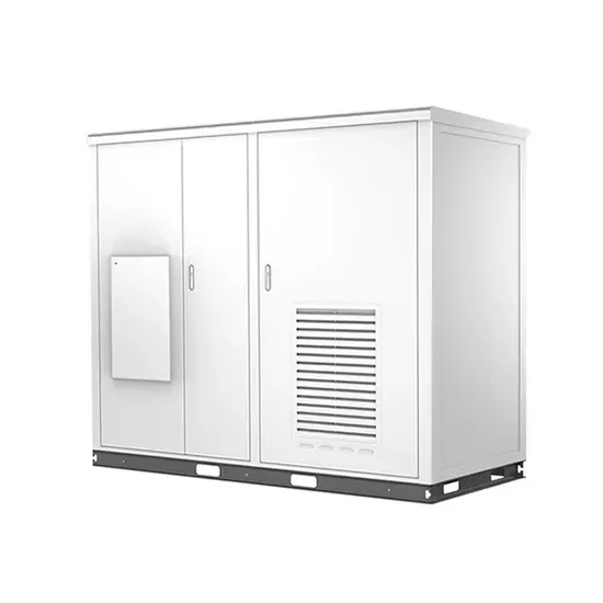
[pdf] List of top verified Solar Energy Companies in Namibia, near me. . NEC (Pty) Ltd is a leading provider of energy and pumping solutions, dedicated to delivering excellence in service and innovation. The NEC Group embarked on a restructure of its operating entities, and we are proudly introducing NEC Energy and NEC Water & Pumps as our core operating entities. This article explores the country's unique solar advantages, innovative storage solutions, and how businesses like EK SOLAR are reshaping renewable energy. . We have a proven track record - we are the leading solar power company in the sunbelt countries where climate conditions are extreme. . A 100 MW solar PV plant by NamPower is under construction in Rosh Pinah Namibia with N$1. 6 billion funding and June 2026 commissioning target. Link copied!Copy failed! The project has secured N$1.
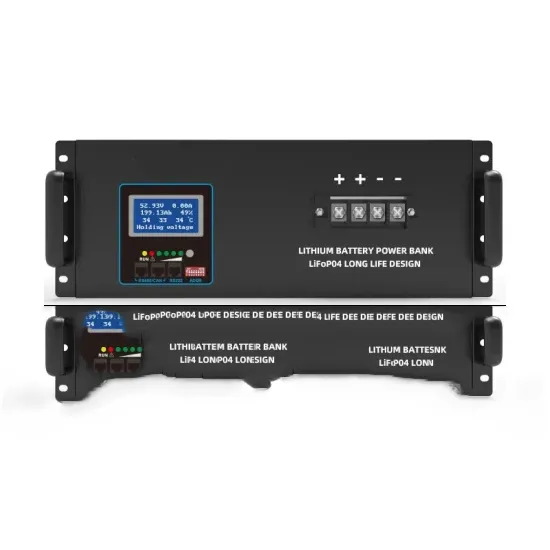
[pdf] The best way to charge a solar battery is by sunlight. Without getting too technical, solar panels let photons (which are light particles) impact electrons and knock them away from atoms. This charges the atoms and generates an electrical flow. The greater the sunlight, the more. . Have you ever wondered how to keep your solar batteries fully charged and ready for use? If you're relying on solar energy, understanding how to charge those batteries efficiently is key to maximizing your investment. To ensure optimal performance when charging with solar, it's important to maintain the. . Solar panels are a great way to charge batteries without relying on the power grid – perfect for camping trips, power outages, or simply cutting down on electricity bills.
[pdf] Energy Digital takes a look at the top 10 biggest solar farms in the world. 10: Kurnool Ultra Mega Solar Park - India. In June 2024, China connected the 3. 5 GW Midong solar project near Ürümqi in Xinjiang to the grid, making it, at that moment, the world's largest single operational PV plant. The installation spans desert terrain and is reported to generate around 6. The capacity of solar farms included ranges from hundreds to. . Largest Solar Farms in the USA (2026) (ranked based on capacity) 1. Copper Mountain Solar Facility 1. These power plants use solar panels to convert sunlight directly into electricity using the photovoltaic effect.
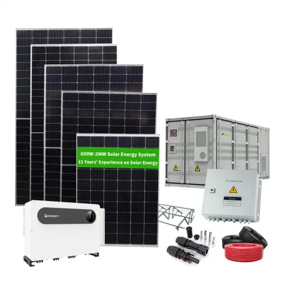
[pdf] This guide includes an overview of the top 5 pure sine wave solar inverters designed for RVs, homes, trucks, and off-grid solar systems. . Shop products from small business brands sold in Amazon's store. HouseAndBeyond is reader-supported. Learn more about our process here Planning long camping, RV, or boat trip? Or working at a. . Did you know that only about 15% of off-grid sine wave inverters actually deliver clean, reliable power exactly like mains electricity? I've tested dozens, and trust me, the difference is huge. The car inverter has a conversion efficiency of greater than 91% during normal working and low no-load losses 【PURE SINE. .
[pdf]